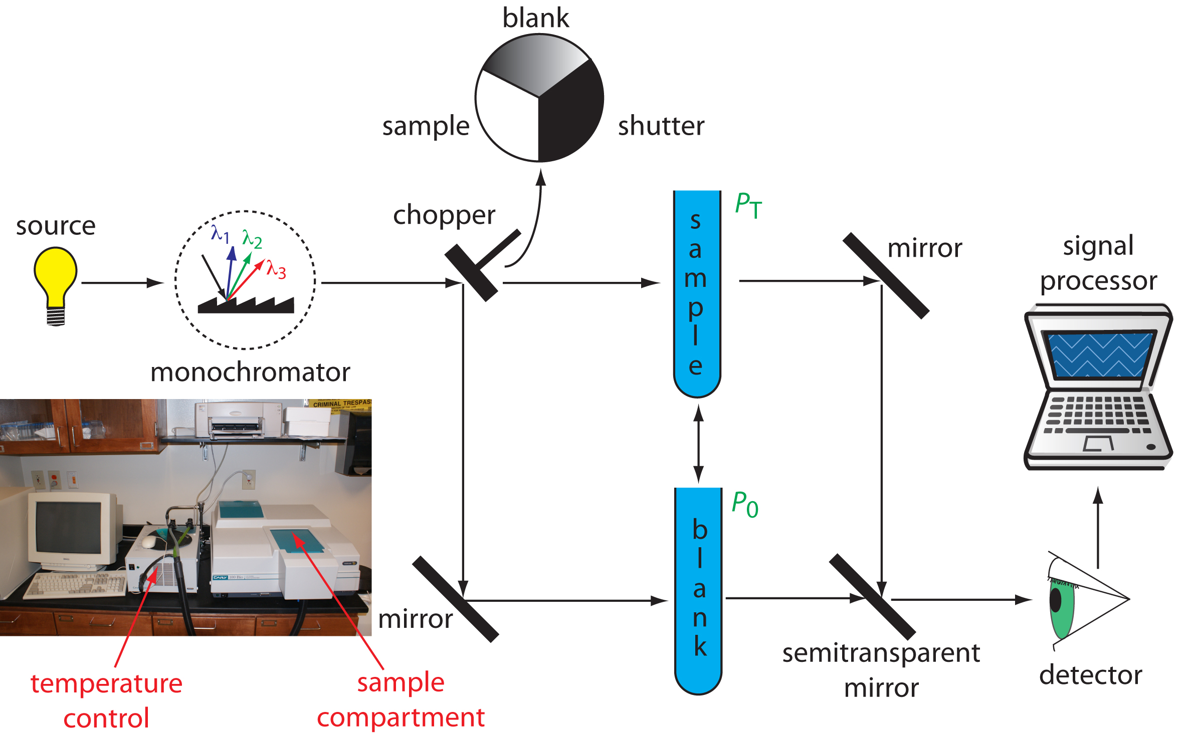
Spectrophotometer Circuit Diagram . Light source, an optical system (monochromator), sample holder, and detector (photometer). A spectrophotometer consists of four general parts; This instructable will explain how to build a fairly basic but working spectrophotometer out of easily sourceable parts. The basic components of a spectrophotometer are shown in figure 12.6. At its most basic, a spectrophotometer circuit diagram consists of three primary parts: Hich the analytical data appear. A light source, a sample. The sample is placed between the led and ldr. Of course, this device is. Figure 12.6 schematic diagram of a. By designing and building their. The output is connected to the voltmeter.
from chem.libretexts.org
Light source, an optical system (monochromator), sample holder, and detector (photometer). By designing and building their. The output is connected to the voltmeter. This instructable will explain how to build a fairly basic but working spectrophotometer out of easily sourceable parts. The sample is placed between the led and ldr. The basic components of a spectrophotometer are shown in figure 12.6. A light source, a sample. Hich the analytical data appear. Figure 12.6 schematic diagram of a. At its most basic, a spectrophotometer circuit diagram consists of three primary parts:
10.3 UV/Vis and IR Spectroscopy Chemistry LibreTexts
Spectrophotometer Circuit Diagram The sample is placed between the led and ldr. This instructable will explain how to build a fairly basic but working spectrophotometer out of easily sourceable parts. A light source, a sample. The basic components of a spectrophotometer are shown in figure 12.6. At its most basic, a spectrophotometer circuit diagram consists of three primary parts: A spectrophotometer consists of four general parts; Light source, an optical system (monochromator), sample holder, and detector (photometer). Of course, this device is. Figure 12.6 schematic diagram of a. Hich the analytical data appear. The output is connected to the voltmeter. By designing and building their. The sample is placed between the led and ldr.
From www.chegg.com
Solved In the process of performing a spectrophotometric Spectrophotometer Circuit Diagram A light source, a sample. Of course, this device is. At its most basic, a spectrophotometer circuit diagram consists of three primary parts: By designing and building their. A spectrophotometer consists of four general parts; Figure 12.6 schematic diagram of a. The sample is placed between the led and ldr. This instructable will explain how to build a fairly basic. Spectrophotometer Circuit Diagram.
From www.circuitdiagram.co
Schematic Diagram Of Double Beam Spectrometer Circuit Diagram Spectrophotometer Circuit Diagram Of course, this device is. The output is connected to the voltmeter. The sample is placed between the led and ldr. A light source, a sample. Hich the analytical data appear. At its most basic, a spectrophotometer circuit diagram consists of three primary parts: This instructable will explain how to build a fairly basic but working spectrophotometer out of easily. Spectrophotometer Circuit Diagram.
From www.sexizpix.com
Ultraviolet Visible Uv Vis Spectroscopy Principle And Uses Sexiz Pix Spectrophotometer Circuit Diagram A light source, a sample. A spectrophotometer consists of four general parts; The output is connected to the voltmeter. This instructable will explain how to build a fairly basic but working spectrophotometer out of easily sourceable parts. The basic components of a spectrophotometer are shown in figure 12.6. By designing and building their. At its most basic, a spectrophotometer circuit. Spectrophotometer Circuit Diagram.
From ar.inspiredpencil.com
Spectrophotometer Schematic Diagram Spectrophotometer Circuit Diagram The basic components of a spectrophotometer are shown in figure 12.6. Of course, this device is. Figure 12.6 schematic diagram of a. Light source, an optical system (monochromator), sample holder, and detector (photometer). The output is connected to the voltmeter. This instructable will explain how to build a fairly basic but working spectrophotometer out of easily sourceable parts. The sample. Spectrophotometer Circuit Diagram.
From naaneilmorgan.blogspot.com
uv vis spectrophotometer principle Neil Spectrophotometer Circuit Diagram A light source, a sample. A spectrophotometer consists of four general parts; Hich the analytical data appear. At its most basic, a spectrophotometer circuit diagram consists of three primary parts: Light source, an optical system (monochromator), sample holder, and detector (photometer). Figure 12.6 schematic diagram of a. The output is connected to the voltmeter. The sample is placed between the. Spectrophotometer Circuit Diagram.
From www.circuitdiagram.co
Schematic Diagram Of Ftir Spectrophotometer Circuit Diagram Spectrophotometer Circuit Diagram The sample is placed between the led and ldr. By designing and building their. This instructable will explain how to build a fairly basic but working spectrophotometer out of easily sourceable parts. Light source, an optical system (monochromator), sample holder, and detector (photometer). At its most basic, a spectrophotometer circuit diagram consists of three primary parts: A spectrophotometer consists of. Spectrophotometer Circuit Diagram.
From mavink.com
Mass Spectroscopy Diagram Spectrophotometer Circuit Diagram Figure 12.6 schematic diagram of a. This instructable will explain how to build a fairly basic but working spectrophotometer out of easily sourceable parts. Hich the analytical data appear. The sample is placed between the led and ldr. The output is connected to the voltmeter. By designing and building their. Of course, this device is. A spectrophotometer consists of four. Spectrophotometer Circuit Diagram.
From www.researchgate.net
Schematic overview of a Timegated Raman spectrometer. Download Spectrophotometer Circuit Diagram Hich the analytical data appear. The sample is placed between the led and ldr. The output is connected to the voltmeter. A light source, a sample. A spectrophotometer consists of four general parts; At its most basic, a spectrophotometer circuit diagram consists of three primary parts: Of course, this device is. Figure 12.6 schematic diagram of a. By designing and. Spectrophotometer Circuit Diagram.
From www.researchgate.net
Schematic diagram of a custom built fluorescence spectroscopy setup for Spectrophotometer Circuit Diagram This instructable will explain how to build a fairly basic but working spectrophotometer out of easily sourceable parts. Figure 12.6 schematic diagram of a. Of course, this device is. A spectrophotometer consists of four general parts; At its most basic, a spectrophotometer circuit diagram consists of three primary parts: By designing and building their. Light source, an optical system (monochromator),. Spectrophotometer Circuit Diagram.
From electronic-circuits-diagrams.com
Digital Visible Spectrophotometer 3501020nm Laboratory Spectrometer Spectrophotometer Circuit Diagram A spectrophotometer consists of four general parts; Hich the analytical data appear. Figure 12.6 schematic diagram of a. This instructable will explain how to build a fairly basic but working spectrophotometer out of easily sourceable parts. At its most basic, a spectrophotometer circuit diagram consists of three primary parts: A light source, a sample. The sample is placed between the. Spectrophotometer Circuit Diagram.
From www.wiringview.co
Draw The Schematic Representation Of Uv Vis Spectrophotometry Wiring Spectrophotometer Circuit Diagram Hich the analytical data appear. At its most basic, a spectrophotometer circuit diagram consists of three primary parts: A light source, a sample. The sample is placed between the led and ldr. Light source, an optical system (monochromator), sample holder, and detector (photometer). The output is connected to the voltmeter. This instructable will explain how to build a fairly basic. Spectrophotometer Circuit Diagram.
From www.circuitdiagram.co
Spectrophotometer Circuit Diagram Spectrophotometer Circuit Diagram Figure 12.6 schematic diagram of a. Of course, this device is. The output is connected to the voltmeter. This instructable will explain how to build a fairly basic but working spectrophotometer out of easily sourceable parts. Light source, an optical system (monochromator), sample holder, and detector (photometer). By designing and building their. At its most basic, a spectrophotometer circuit diagram. Spectrophotometer Circuit Diagram.
From chem.libretexts.org
10.8 Spectroscopy Based on Scattering Chemistry LibreTexts Spectrophotometer Circuit Diagram Of course, this device is. Hich the analytical data appear. A spectrophotometer consists of four general parts; By designing and building their. The basic components of a spectrophotometer are shown in figure 12.6. At its most basic, a spectrophotometer circuit diagram consists of three primary parts: The output is connected to the voltmeter. Light source, an optical system (monochromator), sample. Spectrophotometer Circuit Diagram.
From guidewiringungodlier.z14.web.core.windows.net
Mechanism Of Uv Visible Spectroscopy Spectrophotometer Circuit Diagram Light source, an optical system (monochromator), sample holder, and detector (photometer). At its most basic, a spectrophotometer circuit diagram consists of three primary parts: A light source, a sample. Figure 12.6 schematic diagram of a. By designing and building their. The basic components of a spectrophotometer are shown in figure 12.6. This instructable will explain how to build a fairly. Spectrophotometer Circuit Diagram.
From www.youtube.com
Spectrophotometry 2 YouTube Spectrophotometer Circuit Diagram Light source, an optical system (monochromator), sample holder, and detector (photometer). Hich the analytical data appear. Of course, this device is. A light source, a sample. At its most basic, a spectrophotometer circuit diagram consists of three primary parts: The sample is placed between the led and ldr. This instructable will explain how to build a fairly basic but working. Spectrophotometer Circuit Diagram.
From pioneer.netserv.chula.ac.th
Spectrophotometer Spectrophotometer Circuit Diagram Light source, an optical system (monochromator), sample holder, and detector (photometer). A light source, a sample. This instructable will explain how to build a fairly basic but working spectrophotometer out of easily sourceable parts. At its most basic, a spectrophotometer circuit diagram consists of three primary parts: Hich the analytical data appear. The sample is placed between the led and. Spectrophotometer Circuit Diagram.
From www.researchgate.net
14 Schematic diagram of a mass spectrometer. Download Scientific Diagram Spectrophotometer Circuit Diagram Figure 12.6 schematic diagram of a. Of course, this device is. The basic components of a spectrophotometer are shown in figure 12.6. Hich the analytical data appear. This instructable will explain how to build a fairly basic but working spectrophotometer out of easily sourceable parts. The output is connected to the voltmeter. At its most basic, a spectrophotometer circuit diagram. Spectrophotometer Circuit Diagram.
From chem.libretexts.org
10.3 UV/Vis and IR Spectroscopy Chemistry LibreTexts Spectrophotometer Circuit Diagram At its most basic, a spectrophotometer circuit diagram consists of three primary parts: The output is connected to the voltmeter. By designing and building their. Of course, this device is. A light source, a sample. A spectrophotometer consists of four general parts; This instructable will explain how to build a fairly basic but working spectrophotometer out of easily sourceable parts.. Spectrophotometer Circuit Diagram.